Ductile Iron Pipe Installation Guide: Cutting, Chamfering, and Roundness Correction
2025-06-06 16:56:34 hits:0
During the installation of ductile iron pipes, back - cut chamfering and rounding are crucial steps to ensure the sealing performance and structural integrity of pipe connections. As part of the Ductile Iron Pipe Installation Guide series, this article will provide a detailed introduction to the back - cut chamfering and rounding operations for ductile iron pipes. Combining our technical expertise as a supplier, we will break down every detail of back - cut chamfering and rounding to facilitate efficient overseas project construction!
Before reading this article, we recommend that you familiarize yourself with our previous guides in the Ductile Iron Pipe Installation series to gain a more comprehensive understanding of the installation process.
Key Points and Operational Specifications for the Lifting Process
Stacking and Storage - A Key Step in Safeguarding Pipe Quality

I. Tools and Materials Preparation
Before performing back - cut chamfering and rounding, prepare the following tools and materials:
Cutting tools: We recommend using a portable cutting machine (such as the Poma 983TTA) designed for DN80 - DN2200 ductile iron pipes, which provides precise and efficient cutting to meet different pipe diameters requirements.
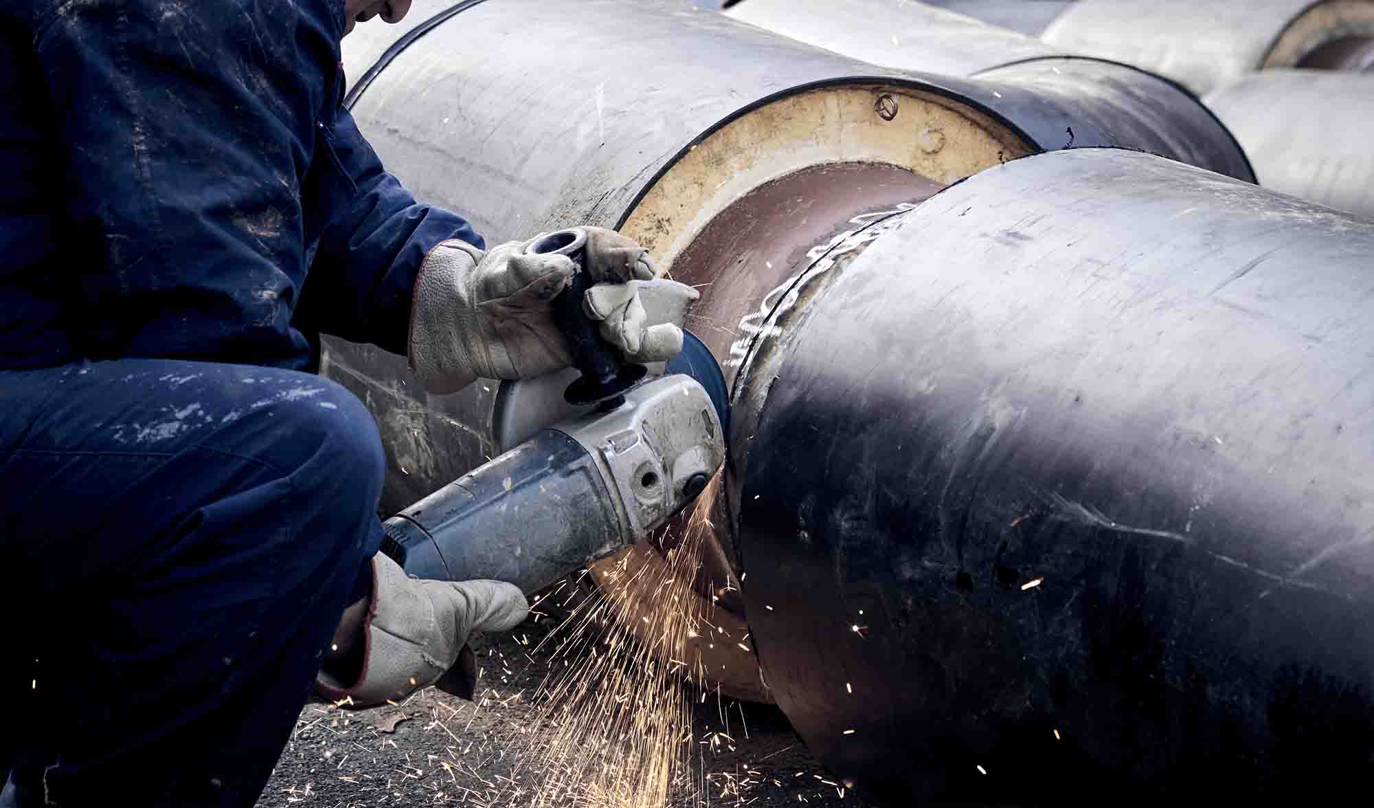
Chamfering tools: An angle grinder (such as the Bosch GWS14 - 150CI) for pipe mouth chamfering to avoid damaging the rubber ring during installation.
Protective materials: Zinc - rich paint and high chlorinated polyethylene.
Other tools: A 5 - ton hydraulic jack, wooden blocks (or adjustable skids), two rubber pads, and a 7.5 - meter tape measure.
II. Practical Steps for Ductile Iron Pipe Back - cut Chamfering
Pipe Cutting Positioning (Key Points: Perpendicular Line Drawing + Dimension Measurement)
Line Drawing: Use chalk to draw a cutting guide line along the circumference of the pipe mouth, ensuring it is perpendicular to the axis. Inclined cutting can lead to misalignment of the interface and affect sealing performance.
Measurement: For large - diameter pipes (e.g., DN1200+), accurately measure the cutting position dimensions. For small - diameter pipes (DN80 - DN600), quick marking is sufficient. Ensure the cutting length is within "2/3 of the pipe length" (avoid excessive cutting to prevent weakening the pipe strength).
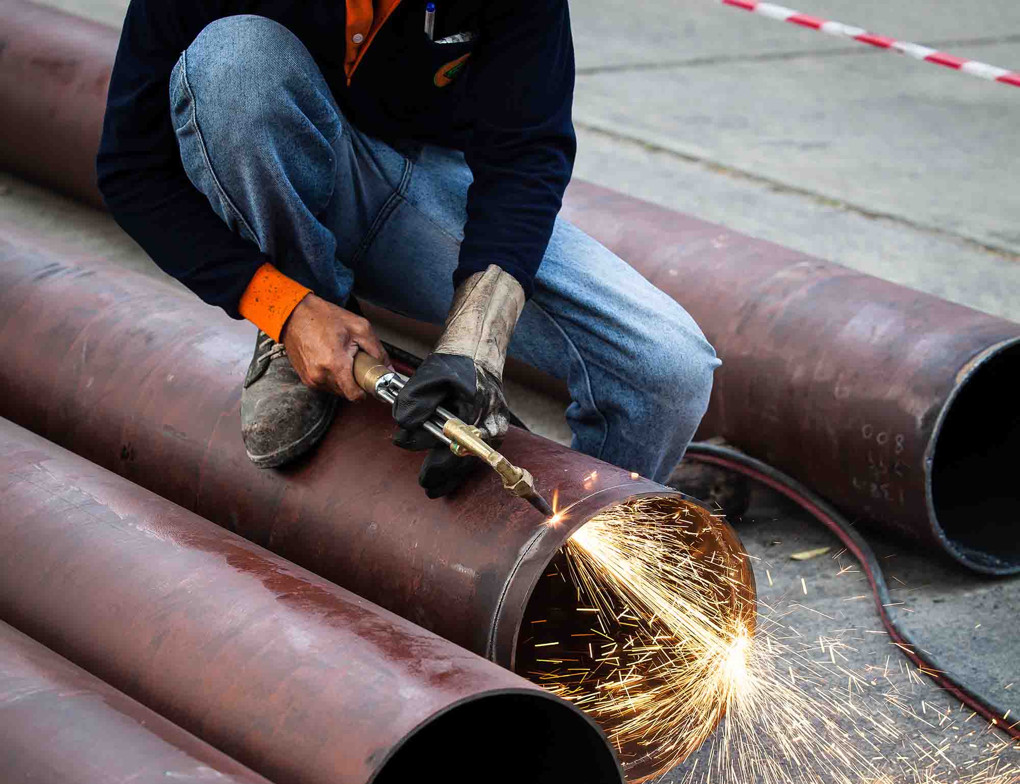
Pipe Cutting Machine Cutting (Core: Secure Pipe + Steady Cutting Speed)
Securely fix the pipe to be cut (using pipe racks or ground anchors for assistance). Start the pipe cutting machine and cut at a steady speed around the pipe. Cutting too fast can result in uneven cuts, while cutting too slow can generate excessive heat and damage the anti - corrosion coating.
Chamfering (Protection Key: Avoiding Rubber Ring Damage)
Chamfer the cut pipe mouth to avoid damaging the rubber ring during installation. Recommended chamfer dimensions (different DN values are associated with different m/n values):
| DN Specification | m(mm) | n(mm) |
|---|---|---|
| DN80 | 6 | 2 |
| DN80 | 9 | 3 |
| DN80 | 15 | 5 |
| DN80 | 20 | 5 |
| DN80 | 20 | 7 |
| DN80 | 23 | 8 |
| DN80 | 26 | 9 |
Applying Zinc - rich Paint and High Chlorinated Polyethylene: Protecting Pipe Lifespan
Steps: After chamfering, first apply zinc - rich paint (to enhance the anti - corrosion base, recommended thickness ≥80μm). Once dry (drying time ≥4 hours at room temperature), apply high chlorinated polyethylene (thickness ≥120μm).
Note: If cement lining damage is found after cutting, repair it according to the "lining repair specifications" (e.g., filling with high - strength cement) before anti - corrosion treatment to avoid future leakage.
Safety Tips:
To ensure operational safety, wear protective glasses, rubber gloves, and other personal protective equipment during pipe cutting.
Hold the pipe ring as cutting nears completion to avoid injury from falling pipe rings.

III. Rounding: Ensuring "Seamless" Pipe Connections
Measuring Ovality and Identifying Non - round Points
Use the formula to calculate ovality, where DM represents the maximum diameter and dm represents the minimum diameter: Ovality = (DM - dm) / (DM + dm)
Allowable ovality standards:
DN80 - DN200: Within DE tolerance range
DN250 - DN600: Not exceeding 1% of DE
DN700 - DN2200: Not exceeding 2% of DE
Rounding (Key Points: Steady Force Application + Lining Protection)
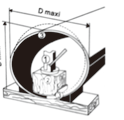
Install tools: Assemble the jack, skids, and rubber pads as shown in the diagram, and apply force to the points of non - roundness. Apply pressure steadily to avoid sudden impact damage to the pipe.
Check lining: During rounding, ensure that the cement lining is not damaged (can be checked with an endoscope or flashlight). Lining damage can reduce the pipe's pressure - bearing and anti - corrosion performance.
Measure the maximum/minimum diameter of the pipe mouth with a tape measure and mark the points of non - roundness to provide a basis for rounding.

For detailed parameters of effective length, joint type, and socket outer diameter DE for different pipe specifications, refer to the following table:
| DN | Effective Length (m) | Joint Type | Socket Outer Diameter DE (mm) |
|---|---|---|---|
| 350 | 6 | TYT | 378 |
| 400 | 6 | TYT | 429 |
| 450 | 6 | TYT | 480 |
| 500 | 6 | TYT | 532 |
| 600 | 6 | TYT | 635 |
| 700 | 6 | TYT | 738 |
| 800 | 6 | TYT | 842 |
| 900 | 6 | TYT | 945 |
| 1000 | 6 | TYT | 1048 |
| 1200 | 6 | Super T - type | 1255 |
| 1400 | 6 | Super T - type | 1462 |
| 1600 | 6 | Super T - type | 1668 |
| 1800 | 6 | Super T - type | 1875 |
| 2000 | 6 | Super T - type | 2082 |
| 2200 | 6 | Super T - type | 2289 |
(Note: DE tolerance range is +1mm.)
By following these steps, you can ensure that the back - cut chamfering and rounding operations for ductile iron pipes meet standards, laying a solid foundation for subsequent pipe installation.
As a ductile iron pipe supplier, we not only provide high - quality pipes but also offer comprehensive installation technical support. We will continue to share articles on ductile iron pipe installation in the future. The next article plans to discuss the repair of internal and external linings, continuing to empower overseas projects. We recommend bookmarking our website and staying tuned!
(Note: The parameters in this article are based on the industry standards for a popular ductile iron pipe from Tiegu. Specific construction should be adjusted according to pipe model and engineering environment to ensure compliance and safety.)

About Us
Tiegu, as a global supplier of ductile iron pipes, is committed to providing high - quality ductile iron pipes and supporting solutions for municipal engineering, water conservancy construction, industrial pipelines, and other fields worldwide. We have a comprehensive product system covering DN80 - DN2200 specifications, a professional technical team, and a well - established logistics network to ensure that every ductile iron pipe complies with international standards from production to installation.
If you have procurement needs for ductile iron pipes or other castings, please contact us immediately to get quotes and assistance for ductile iron pipes and castings:
By standardizing back - cut chamfering and rounding, your ductile iron pipe project can effectively avoid potential risks such as interface leakage and rubber ring damage. This is our commitment as a supplier to ensuring the quality of the entire chain of "product + service". We look forward to in - depth communication with you in the subsequent installation process!

 en
en  fra
fra  de
de  ru
ru  ara
ara  gle
gle  it
it  jp
jp  kor
kor  th
th  zh
zh 


